
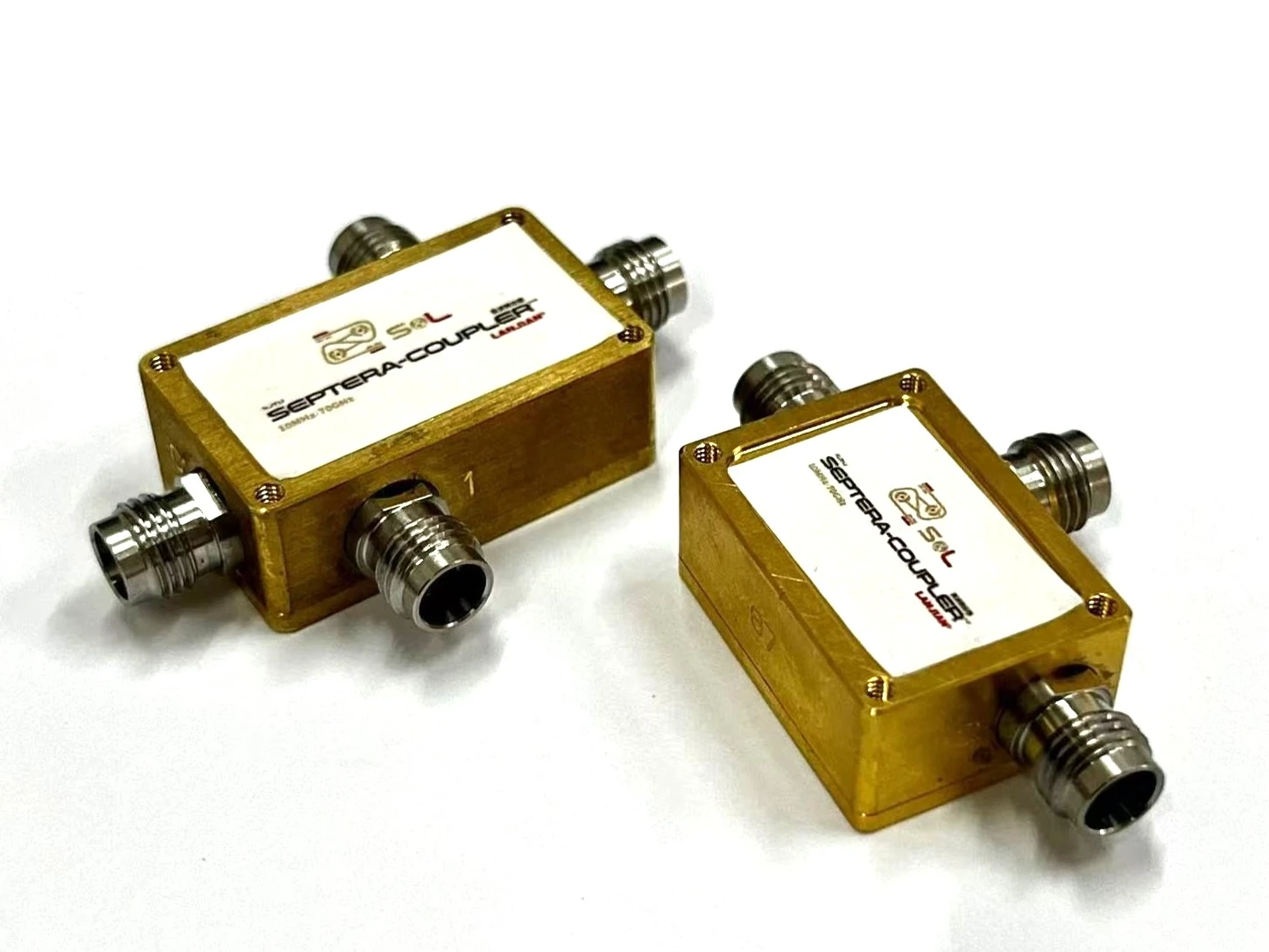
Directional Couplers
Two structures — unidirectional and bidirectional sampling — both with a 10 MHz lower limit on the main line, 12 dB typical coupling and 15 dB typical directivity.
- Main-line Frequency Range10 MHz – 145 GHz
- Typical Coupling12 dB
- Typical Directivity15 dB
Model Comparison
| Model | Type | Frequency Range | Main-line Insertion Loss | Status |
|---|---|---|---|---|
| SC12-67-01 | Unidirectional | 0.01–67 GHz | 2.0 dB max | In Production |
| DC12-67-01 | Bidirectional | 0.01–67 GHz | 2.5 dB max | In Production |
| SC12-110-01 | Unidirectional | 0.01–110 GHz | 2.7 dB max | In Production |
| DC12-110-01 | Bidirectional | 0.01–110 GHz | 2.9 dB max | In Production |
| DC12-145(130)-01 | Bidirectional | 0.01–145 / 130 GHz | 3.75 / 3.0 dB max | Sample |
Click a model to jump to its specifications and curves below.
MODEL SC12-67-01 67 GHz Unidirectional Directional Coupler Compact unidirectional directional coupler for VNAs up to 67 GHz, with coupled-port isolation better than 59 dB from 10 MHz.
Electrical Characteristics
| Main-line Frequency Range | 10 MHz – 67 GHz |
|---|---|
| Coupling | 12 dB typical |
| Main-line Insertion Loss | 2.0 dB max |
| Main-line VSWR / S11 | 1.7 max / ≤ −11.7 dB |
| S31 at 10 MHz | > −59 dB |
| Directivity | 15 dB typical |
Mechanical & Interface
Overall envelope 40.61 × 25.71 × 11.20 mm (67 GHz package)
Test Data
MODEL DC12-67-01 67 GHz Bidirectional Directional Coupler Provides forward and reverse coupled sampling in a single package to monitor incident and reflected waves simultaneously.
Electrical Characteristics
| Main-line Frequency Range | 10 MHz – 67 GHz |
|---|---|
| Coupling | 12 dB typical |
| Main-line Insertion Loss | 2.5 dB max |
| Main-line VSWR / S11 | 1.50 max / ≤ −14 dB |
| S31 at 10 MHz | > −59 dB |
| Directivity | 15 dB typical |
| Coupling-port Isolation | 50 dB min |
Mechanical & Interface
Overall envelope 45.35 × 33.37 × 11.20 mm (67 GHz package)
Test Data
MODEL SC12-110-01 110 GHz Unidirectional Directional Coupler Unidirectional coupler covering up to 110 GHz, sharing the package family with the 67 GHz models for easy mechanical interchange within a system.
Electrical Characteristics
| Main-line Frequency Range | 10 MHz – 110 GHz |
|---|---|
| Coupling | 12 dB typical |
| Main-line Insertion Loss | 2.7 dB max |
| Main-line VSWR / S11 | 1.7 max / ≤ −11.7 dB |
| S31 at 10 MHz | > −59 dB |
| Directivity | 15 dB typical |
Mechanical & Interface
Overall envelope 40.61 × 25.71 × 11.20 mm; 110 GHz interface configuration to be confirmed at order
Test Data
MODEL DC12-110-01 110 GHz Bidirectional Directional Coupler 110 GHz bidirectional coupler with coupling-port isolation improved to 55 dB min, ideal for sampling incident and reflected power simultaneously.
Electrical Characteristics
| Main-line Frequency Range | 10 MHz – 110 GHz |
|---|---|
| Coupling | 12 dB typical |
| Main-line Insertion Loss | 2.9 dB max |
| Main-line VSWR / S11 | 1.58 max / ≤ −13 dB |
| S31 at 10 MHz | > −59 dB |
| Directivity | 15 dB typical |
| Coupling-port Isolation | 55 dB min |
Mechanical & Interface
Overall envelope 40.61 × 25.71 × 11.20 mm; 110 GHz interface configuration to be confirmed at order
Test Data
MODEL DC12-145(130)-01 145 / 130 GHz Bidirectional Directional Coupler One platform offers both 145 GHz and 130 GHz configurations, with insertion loss specified according to the interface type.
Electrical Characteristics
| Main-line Frequency Range | 10 MHz – 145 / 130 GHz |
|---|---|
| Coupling | 12 dB typical |
| Main-line Insertion Loss | 3.75 / 3.0 dB max |
| Main-line VSWR / S11 | 1.44 typical / ≤ −15 dB typical |
| S31 at 10 MHz | > −59 dB |
| Directivity | 15 dB typical |
| Coupling-port Isolation | 47 dB min / 50 dB typical |
Mechanical & Interface
Package dimensions follow the assembly drawing of the ordered 0.8 mm / 1.0 mm configuration
Test Data
Need a coupler for a specific band or interface?
Specific band plans and interface types from 10 MHz to 145 GHz can be customized. Please provide your target bands and system topology and we will respond after evaluation.