
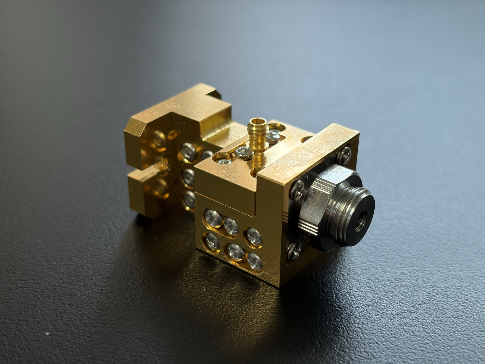
Diplexers
Combines a coaxial main line and a millimeter-wave extension path into a single test port — a key passive component of band-stitching systems. Current products cover 10 MHz–170 GHz.
- Band Split10 MHz–67 / 67–110 GHz; 10 MHz–110 / 110–170 GHz
- In-band Insertion Loss (max)2.0 / 2.5 dB; 2.5 / 4.0 dB
- Crossover Insertion Loss5.5 dB / 6.3 dB typical
- Common-port Return Loss14 dB min
Model Comparison
| Model | Band Split | LPF / HPF Insertion Loss (max) | Typical Crossover Insertion Loss | Status |
|---|---|---|---|---|
| DIP-67-110 | 10 MHz–67 GHz / 67–110 GHz | 2.0 / 2.5 dB | 5.5 dB | In Production |
| DIP-110-170 | 10 MHz–110 GHz / 110–170 GHz | 2.5 / 4.0 dB | 6.3 dB | In Production |
Click a model to jump to its specifications and curves below.
MODEL DIP-67-110 110 GHz Diplexer Combines the 10 MHz–67 GHz coaxial path and the 67–110 GHz extension path into a single test port — the core passive component of a 110 GHz band-stitching system, validated on a full system in 2024.
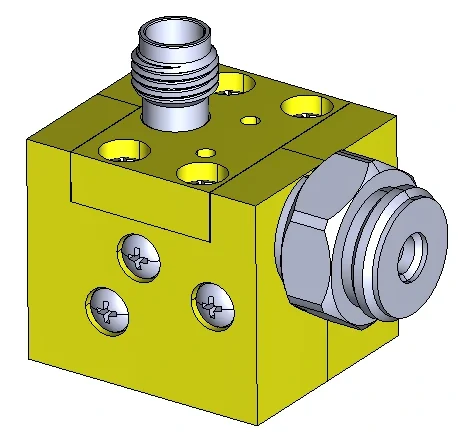
Package render
Electrical Characteristics
| LPF / HPF Bands | 10 MHz–67 GHz / 67–110 GHz |
|---|---|
| LPF / HPF Insertion Loss (max) | 2.0 dB / 2.5 dB |
| Typical Crossover Insertion Loss | 5.5 dB |
| Common-port Return Loss | 14 dB min |
Mechanical & Interface
Package dimensions follow the 110 GHz assembly drawing
Test Data
MODEL DIP-110-170 170 GHz Diplexer Routes the 110–170 GHz waveguide path into the 10 MHz–110 GHz coaxial main line, combining a near-170 GHz extension module and the baseband path into a single test port.
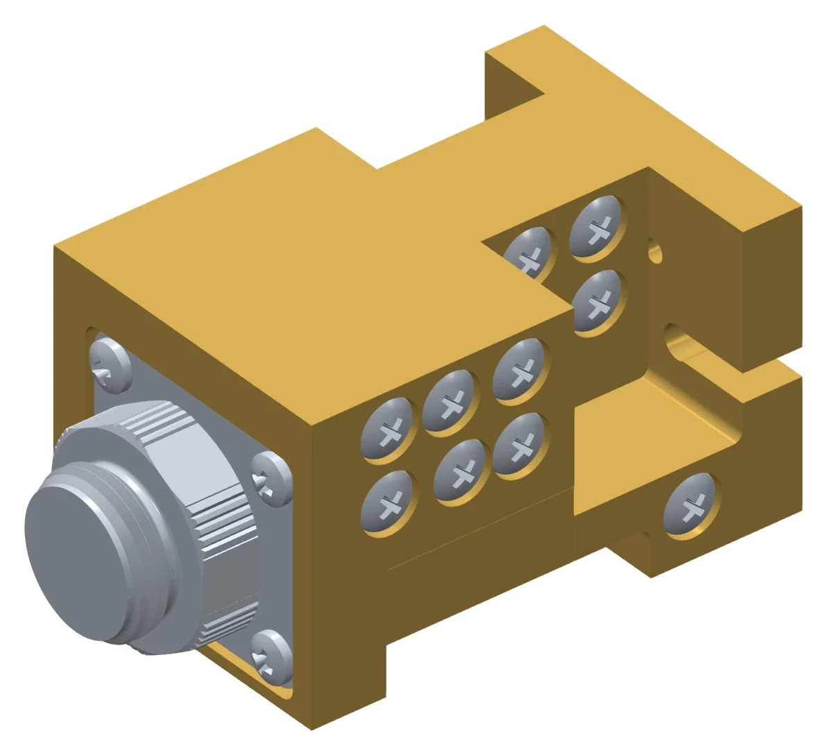
Package render
Electrical Characteristics
| LPF / HPF Bands | 10 MHz–110 GHz / 110–170 GHz |
|---|---|
| LPF / HPF Insertion Loss (max) | 2.5 dB / 4.0 dB |
| Typical Crossover Insertion Loss | 6.3 dB |
| Common-port Return Loss | 8 dB min / 10 dB typical |
Mechanical & Interface
Overall envelope 43.06 × 23.21 × 20.97 mm
Test Data
Usage Notes
The following points are for reference in system design only.
Passive and bidirectional
The diplexer is a passive component (the functional direction shown is combining) and can also be used in reverse to split two bands.
Budget the crossover loss separately
When budgeting power at the band boundary, use the standalone crossover insertion loss (5.5 dB for DIP-67-110, 6.3 dB for DIP-110-170); in-band insertion loss alone does not describe this region.
Include the diplexer in calibration
The diplexer sits between the common test port and each sampling branch, so the calibration of every branch must include the diplexer response in the reference plane.
Need a custom crossover frequency?
Crossover frequency, in-band flatness and port types can all be tailored to the system. Please provide your target bands and system topology and we will respond after evaluation.